Project – Modern 3 Way Mic Switch Box
 Why build a mic switch unit? One of the problems with having multiple radios and one or two favourite microphones is the ability to use those mics with any of the radios.
Ready built mic switch units are available, but none that I looked at really suited my needs, thus the idea to design and construct a custom solution formed.
My requirements were that I could use either the same standard fist mic, desk mic or studio mic with whichever radio I wanted to use at the time. I concluded that my favourite mics were my Yaesu MD-200 and my Kenwood MC-60.
The first hurdle is the fact that although both mics share an 8 pin connector, the wiring is slightly different. Then I also want to use them with my Icom 756 ProIII which feeds a voltage on the audio signal pin which requires blocking.
The easiest method of constructing a mic switch would have been to simply put a couple of plugs on a box with a multipole, 3 way switch, my idea for version 1.
Yes, I do mean plugs, allow me to explain; most people refer to the connector on the radio as a mic socket and the connector on the mic cable as a plug. This is technically incorrect as the “plug” is actually the socket, likewise the “socket” is a plug when defined by the pins and receptacles – take a look and think about it.
Deciding this wouldn’t be the best option, coupled with the difficulty in obtaining a suitable mic switch, I embarked upon designing the electronic switching and logic circuits, version 2 of the project.
The current design has two inputs, input 1 being wired for use with Yaesu mics, and input 2 wired for Kenwood wired mics. The are three outputs, one each for Yaesu, Kenwood and Icom.
With the basic mic switch circuit designed, I then added an auto-power function using the voltage output available on all my radios. This simply turns the unit on whenever a radio is powered up, and turns the unit off when the radios are all off.
This electronic power switch has been designed so that it can also be used to control power to external devices, currently planned for controlling the power supply to my remote auto ATU.
I used the Altium PCB design software to create my PCB design. Altium Designer allows you easily place the components on the PCB and then route the tracks on both the top and bottom of the board.
Once the design is completed it was then sent to JLCPCB to produce my prototype PCB’s which arrived within a week of ordering.
 After building the first electronic prototype unit, I made a few component and circuit changes and completely redesigned the PCB, making it both smaller and neater.
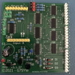
The main picture at the top of this page shows version 3 of the mic switch project with the components soldered into place.
Some eagle-eyed may spot that currently components C3 and C4 are unpopulated, these two capacitors are simply to eliminate “key bounce” on the front panel control buttons, their value to be determined by a bit of trial and error, and can also be soldered directly across the switch instead of on the PCB.
I’m in the process of designing a method to enable an “any-to-any” scenario, however this requires some quite complicated logic and switching, but I’m quietly confident version 4 will be born fairly soon.
I have a PC headset that I want to monitor two radios at the same time and select one to transmit on. I have seen the MFJ-1262 but it does not allow monitoring of both radios. Having one ear have one radio and the other ear the other radio would be great. So can your board do that or be modified to do it? How do we get the layout or board to build your setup?
No my switch can’t do monitoring of two radios at the same time, I designed purely for switching of the microphone and up/dn etc wiring. I suppose it would be possible to design some sort of headphone switching/combining circuit.
Hi Roger. Can you share the schematic of your current mic switch box? Did you find you had to switch both the hot and ground sides or were you able to use a common ground? Thanks.