Yaesu FT-747 Digimodes Modification
Without using a mass of tangled wires and various connectors, the ageing Yaesu FT-747GX has no easy method of connecting a PC to allow the use of digimodes, here’s how to modify the FT-747.
As with all modifications I accept no responsibility for any damage to you or your equipment through following, or attempting to follow, the information given here. This information is for reference purposes only.
If you don’t feel confident working inside your radio – find someone with enough experience to carry out any work for you.
The CAT socket on the radio is quite useful thus I decided not to make any modifications to this.
Instead the decision was made to use the front panel microphone socket for the connection to the home made interface.
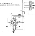
Microphone socket wiring

As can be seen in the schematic diagram, Pin 2 of the mic socket is tied to ground.
This pin is normally used as a common ground for the “Up” and “Down” buttons on the microphone.
Therefore it makes sense to use this pin and simply connect the corresponding wire within the microphone plug to either pin 7 or pin 5 as these are both tied to ground.
With the top cover removed, the front panel can be released from the bottom panel. The front panel will tilt enough to work on the rear of the mic socket without any wiring disconnections.
A short black jumper wire is connected between pins 2 and 5. After de-soldering this wire from pin 2, carefully cut it from pin 5 and remove it.
Using a length of screened audio cable, solder the centre to the free pin of the mic socket. The screen can be either insulated here or connected to pin 7 – mic ground.
If you connected it to pin 7, then the other end will be insulated. Make sure you only connect the screen to ground at one end, NOT both! The reason for only connecting one end is prevent a ground loop.
Route this cable round the right hand side of the radio, following the route of existing wiring.
Rear panel connection
![]()
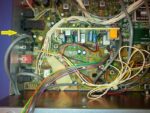
Looking at the rear panel you will see a phono socket marked “AF OUT”. This socket is where the audio output to the PC will be sourced.

From inside the radio, the socket can be seen mounted on the PCB (shown by the yellow arrow).
This point is used to connect the screened cable.
Each phono socket has two small metal parts. The square piece nearest the back panel is the ground connection. Solder the shield of the screened cable to this, ONLY if it’s not grounded at the mic socket end.

A small thin metal contact can be seen running down the back of the socket to the PCB. Solder the center conductor of the screened cable to this point.
Caution! Do not use too much heat when soldering as the plastic socket housing may melt. Also ensure that the cable is correctly soldered to the AF Out socket.
Interface cable wiring
Finally, construct an interface cable with these pin connections (mic plug):
- N/C
- RX Audio Out to PC soundcard input
- N/C
- N/C
- N/C
- PTT
- Ground
- TX Audio In from PC soundcard output
Once this is done, reassemble the radio, hook up your PC, load the software and get digi-moding…
Please leave any comments below if you have tried this mod and had success or otherwise…
Hello! What gives the PTT signal to the radio?
The PTT is CAT controlled – sorry, I should have included the information.
Thanks! And what plug do you use at the microphone socket? What is the connector name?
Thank you!
No problem, the connectors are known as Aviation or GX16 style – here’s a link to some on Amazon https://www.amazon.co.uk/gp/product/B07NYYKQVZ