TS-2000 Display Colour Change
 As standard the Kenwood TS-2000 is shipped with an amber display, while the backlights for the keys are green in colour. This how-to shows you how to change the amber display to almost any colour you want. Colour options are only limited by the LED’s available.
As with any mod or repair, if you’re not confident working with SMD components, don’t attempt the work, making a mistake could result in a ruined TS-2000. Doing this mod will void any warranty you have.
You will require 3 x SMD 330 ohm resistor in a 2010 package – preferably thick film 0.75 Watt and 6 x Ultra bright 3mm LED’s of the required colour.
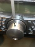 The first step in performing the LED change is remove the outer case of the TS-2000. This involves removing 14 screws and the side handle.
Follow by removing all the knobs from the front panel, these simply pull off with the exception of the VFO knob.
To remove the VFO knob you need to slide the rubber ring from the knob by pulling it forward – it may be tight and you may need a blunt object to prise it off. The knob is secured to the shaft by a small hex-head screw which needs to be loosened slightly.
Remove the screw from the recess above the VFO spindle. Remove the nut from the VFO spindle, along with the spring washer, locking washer and VFO tension lever mechanism.
Removing The Front Panel
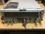 Very carefully unclip the 6 tags securing the front panel, 3 on the top & 3 on the bottom – these do break easily! – and remove the front panel and place to one side.
There are some clear plastic inserts behind some of the buttons so make sure you don’t lose them.
The VFO control is loose and will drop away as the panel is removed. Do not attempt to pull the VFO control wires from the aperture in the chassis as they may have a cable tie to hold the wires in place behind the chassis.
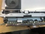 At this point, some people who perform this mod remove the entire front chassis panel. This is unnecessary as the display is easily removed by removing the four screws securing the display to the chassis panel.
Carefully lift the display forward and detach the ribbon cable on the rear of the display by gently pulling it. Do not use excessive force. The display is now free from the radio which can be put to one side.
Desolder old lamps
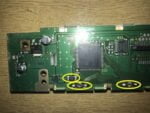

 The next stage is to remove the 6 bulbs and the three 5.6 ohm SMD resistors from the display board.
When desoldering the bulbs it may be wise to desolder one lead, bend it up so it can be held by tweezers or similar when desoldering the second lead. The reason for this is that the bulbs are small enough to fall inside the display, which may then require complete disassembly of the display to retrieve them.
Care should also be taken if the bulbs are removed before the resistors as they could also fall into the bulb holes.
 Three SMD 330 ohm resistors now need to be fitted to replace the resistors that were previously removed. The value of these resistors may have to be varied slightly depending on the voltage of the LED’s used.
To calculate the resistance required, you need to know the rated voltage for the LED, most require 3.3 volts. As the voltage for the illumination is approx 10 volts and the LED’s are connected in serial as pairs, this gives us a voltage requirement of approx 6.6 volts. Thus 330 ohm resistors are required.
Installing The LED’s
The leads of the LED’s have to be bent to just over 90 degrees, as close to the body as possible and cut to approx 3-4mm in length.
The reason for bending the leads greater than 90 degrees is that the lip on the body of the LED sits on the display PCB and the leads will not be in close contact with the solder pads.
The Anode of each LED (long lead) must be fitted towards the resistor.
Once all LED’s and resistors are fitted, re-assemble your TS-2000 which is simply a reverse of dis-assembly, taking care when inserting the ribbon cable into the connector on the display panel.
Before replacing the front panel, check you have no dust or dirt particles on the inside of the display window. If dust/dirt is present clean it using a compressed air canister, such as those for cleaning keyboards. If compressed air isn’t available, use a lint free cloth being extremely gentle so as not to scratch the inside surface.
The VFO tension components are replaced in the following order: Tension spring with the pads facing outwards and the operating lever at the bottom of the radio. This is then followed by the spring washer, and then the shakeproof (crinkly) washer followed by the securing nut. Tighten the nut just enough to prevent it coming undone when operating the tension lever.
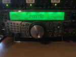 Refit the remainder of the control, the outer cases and handle, connect the power, antenna and any other accessories, turn your TS-2000 on and enjoy your new colour display.