Antennas For 2017
 Now at my new QTH I have much more room in which to play with different antennas. The garden I have at my disposal now would be the envy of a lot of radio amateurs. I am able to erect a full size 80m dipole – that’s 40m in length!
The antenna cables for both HF and VHF/UHF are coaxial, type RG213. This cable is approx 10mm in diameter and fairly low-loss. Better cable is available, however, the RG213 is suitable for my needs.
My shack is one side of the grassed area of the garden and the antennas are the other side. This equates to a distance of approx 40 feet.
 In order to keep things neat and tidy, or at least, to prevent anyone tripping over the cables, a suitable length of flexible pond hose is buried in a shallow trench. All three lengths of coax are routed through the hose.
The current antenna system consists of three antennas. A Hustler 5-BTV vertical antenna, a homebrew fan (or multiband) dipole, both for HF. Also a Watson 7900 VHF/UHF mobile antenna with a homebrew counterpoise system.
 The Hustler 5-BTV sits quite nicely between two young apple trees. It serves as a 6 band vertical antenna. I have installed ground radials, not as many as I would like. The radials comprise of over 100m of wire in use as the counterpoise.
If you look carefully at the picture you can see the 17m modifaction to the right of the antenna – details of how to make the modification can be found here.
A large oak tree serves as nice, reasonably high mounting point for the VHF/UHF antenna. A mobile 2m/70cms co-linear antenna is mounted on a homebrew counterpoise comprising of four radials. Each radial being 1m in length and 6mm solid aluminium rod.
The coverage for VHF/UHF is quite reasonable for a simple antenna. I can access the GB3WR repeater located approximately 40 miles to the north-east. Also GB3JL approx 60 miles to the south west. The fact that my station is around 140m above sea level probably helps a bit!
I keep toying with purchasing a “proper” base station VHF/UHF co-linear. While the “temporary” antenna is working satisfactorily I’m reluctant to change things.
 A fan dipole has been constructed to cover 80m, 40m, 20m, 12m & 10m. The 15m band is available by using the 40m elements on their 3rd harmonic.
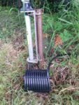
To help reduce any common mode current problems that may occur, each antenna has a simple air cored choke (or ugly balun) as close to it as possible. These are simply a few turns of coaxial cable wound in the form of a coil.
 The one pictured here is located at the base of the Hustler, the mounting post of which can also be seen. Both other chokes are of similar construction. The choke for the dipoles is situated at the bottom of the support pole. Ideally, it would normally be mounted closer to the antenna.
The reason for this is that my QTH backs onto open countryside and we often get quite strong winds blowing across the fields, and so I wanted to keep the wind resistance of the pole down to a minimum. To assist in this I have also routed the coax feeder cable through the inside of the pole up to the dipole center feed point.
It’s too stiff to bend easily! Take that however you like 🙂
A downside of using the heavy RG213 coaxial cable is that it’s awkward to bend into tight corners. This is especially true at the connector on the rear of the radios where it may also place undue strain on the connector to PCB contact inside the radio.
 To overcome this problem I have terminated the incoming coax cables with standard PL259 plugs and by using SO239 to SO239 (female to female) adapters connected lengths of mini-rg8 coax.
The mini rg8 has almost the same characteristics as the larger RG213 but being roughly half the diameter makes it a lot easier to manipulate.
Update July 2017:
I was considering construction of a change-over switch for the HF radios and antennas. IE: being able to switch radio 1 using antenna A and radio 2 using antenna B, changing over to radio 1 using B & radio 2 using A.
Design for such a switch is quite simple. All that is required is a DPDT switch, a suitable mounting box and connectors. It must be borne in mind that the switch is rated at a suitable current level.
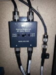
While in the process of sourcing parts to construct the switch I required, I was fortunate enough to stumble across a ready made item. The MFJ 1703 is marketed as a safety switch.
I was already aware these switches were available. Finding one was a different matter, hence the reason for planning to build my own.
 The MFJ 1703 is now fitted in place of the SO239 to SO239 adapters used to join the RG213 to Mini-8 HF antenna cables. Because the original position of the cable joins was tucked away under the worktop, the switch has had to be mounted in their place.
Consequentially, I have to reach to effect the change over. Not too much of a problem as I don’t envisage changing antennas very often!
With thanks! Valuable information!